Example Applications
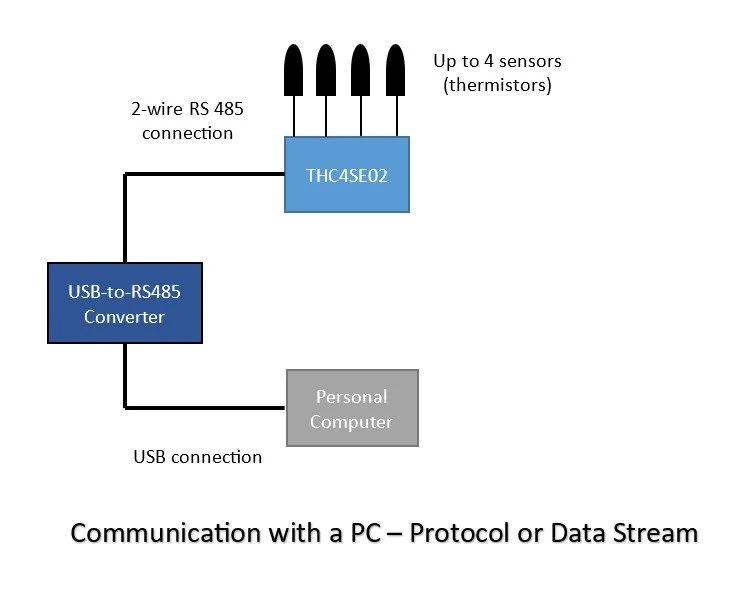
Communication with a PC
In this simple use case, THC4SE02 is connected to a PC for monitoring and data collection. With one device connected, Data Stream (ASCII or Binary) and (ModBus) Protocol methods of communication can be utilized. Multiple of THC4SE02 are also possible with the same daisy chain connection as demonstrated in one of the other application cases below. When multiple THC4SE02 devices are connected in one network, only Protocol method of communication is available.Communication in a Network
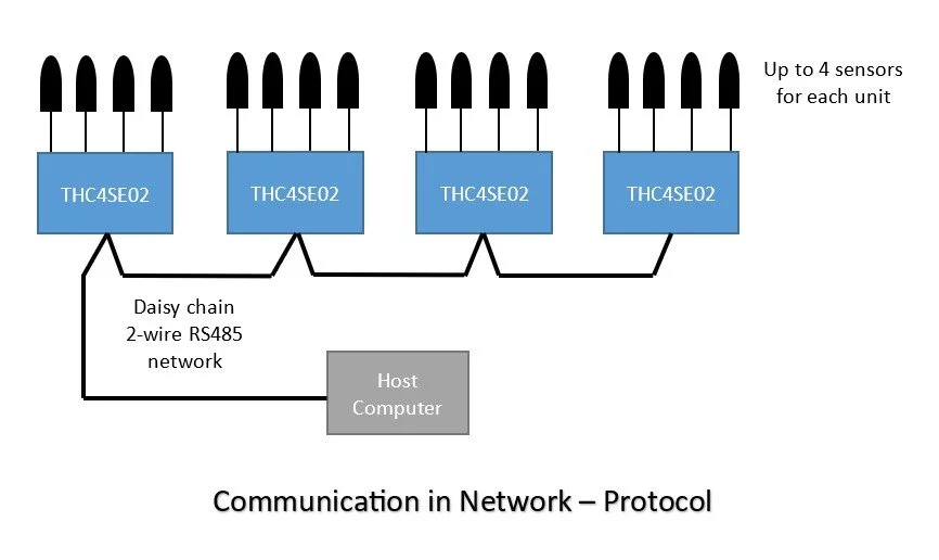
It is possible to use multiple THC4SE02 devices in a RS485 network, communicating to a Host Computer for long cable lengths from 3-feet to hundreds of feet. The connection type is commonly referred as the daisy chain (parallel) connection. Only (ModBus) Protocol communication method is available for data collection and monitoring. The devices can be addressed from 1 to 254. Total number of devices that can be placed in the same network is 128. This allows up to 512 temperature sensors to be read. Communication in an Embedded System
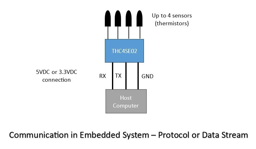
In this use case, THC4SE02 is used in an embedded system application, where it interfaces with a Host Computer (microcontroller). It can be connected with one of the 5VDC or 3.3VDC digital connection options with the proper configuration of THC4SE02. Digital RX/TX signals are buffered, overcurrent, overvoltage and ESD protected. All methods of communication (ASCII Data Stream, Binary Data Stream, and Protocol) are available for use in data collection and monitoring. Networking is possible with the use of Protocol method of communication in this configuration as well. However, maximum number of devices connected will depend on a given embedded system they are used in.Communication in an Embedded Network
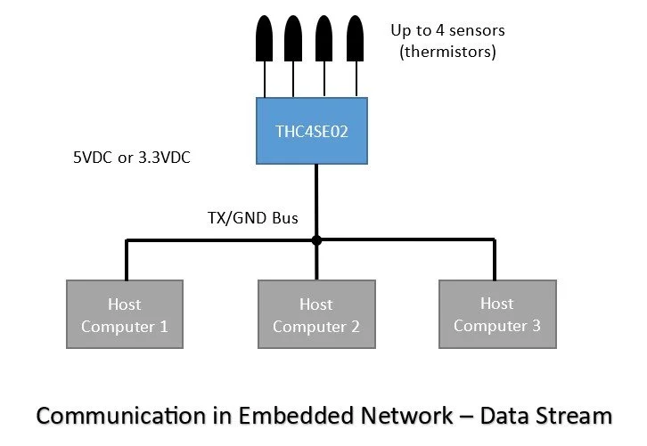
In this embedded system application, THC4SE02 either will be mounted on the same board with the host computers (microcontrollers) or will be in a very close proximity to them, where 5VDC and/or 3.3VDC TX lines can be connected to the host computers to receive temperature data stream either in ASCII or Binary formats. Digital RX/TX signals are buffered, overcurrent, overvoltage and ESD protected. Maximum number of devices connected will depend on a given embedded system they are used in.Data Stream Network Options
THC4SE02 can meet variety of monitoring and datalogging requirements. Once ASCII or Binary data stream is selected, the data will be available on all three serial interfaces at the same time: RS485, 5VDC UART and 3.3VDC UART. These outputs can be connected to different host computers. UART outputs will need to be in a very close proximity to them or THC4SE04 will need to be mounted on the same PCB, whereas RS485 output can be hundreds of feet away. RX/TX signals are buffered, overcurrent, overvoltage and ESD protected. Maximum number of devices connected will depend on a given embedded system they are used in for the 5VDC and 3.3VDC UART outputs.Thermistor Characteristics & Accuracy
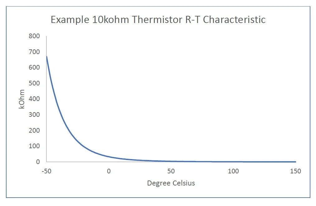
Thermistors are commonly used as temperature sensors. Their repeatable resistance sensitivity to temperature and ease of manufacturability what makes them suitable for temperature measurement. There are two types of thermistors, one is the Positive Temperature Coefficient (PTC) thermistor and the other is the Negative Temperature Coefficient (NTC) thermistor. The resistance of PTC thermistors increases with increase in temperature, hence the name positive. The resistance of NTC thermistors decreases with increase in temperature, hence the name negative. PTC thermistors generally used in current limiting applications in power supplies since increase in current generates heat on PTC thermistors, therefore, limiting current or causing open circuit condition and protecting power supplies. NTC thermistors mainly used in temperature measurement applications. It is common to find them built into probes, a type of environmentally sealed capsule. They are also referred as thermistor probe or temperature probe. A thermistor as a probe is easily adaptable to many different applications such as measuring a HVAC coil temperature, measuring the temperature of a liquid in a chemical process or measuring a heat sink temperature of a power inverter. NTC thermistors have a few different curve types. The most common one and the suitable one for wide temperature measurements is the J-type curve. J-type curve has a negative exponential resistance versus temperature characteristic as shown in the example above.One of the parameters thermistors are quite often defined by is a parameter called Beta. Equation used in Beta calculation is given below.β = ln (R1 / R2 ) / (1 / T1 - 1 / T2 )In a comprehensive datasheet, a thermistor manufacturer will include tabulated resistance versus temperature values. Resistance values are usually provided as the nominal values indicating their ideal values corresponding to a particular temperature. Temperature Coefficient (TC) is also provided in the form of a percentage change of resistance per degree Celsius (% / °C) at a given temperature (slope of the R-T curve). The following is the equation defines the TC, which is also referred as alpha. For NTC thermistors, TC has a negative sign.TC = (dR ⁄ dT) / R × 100 [%]For example, USP10973 thermistor probe can be used as a temperature sensor in Mavi Circuits’ temperature measurement devices. USP10973 has a TC of -4.39%/°C at 25°C and a temperature accuracy of ±0.2°C. Based on this information, the resistance tolerance is calculated as follows:Resistance Tolerance [± % ] = |TC| x Temperature AccuracyResistance Tolerance @ 25°C = 4.39 [%/°C] x 0.2 [°C] = ±0.878% – listed as 1%Or inversely, from resistance tolerance and temperature coefficient at 25°C, we can calculate the temperature accuracy of the thermistor for a wide range of temperatures (such as 0°C to 100°C) as follows:Temperature Accuracy [± °C ] = Resistance Tolerance / |TC| Temperature Accuracy = 1 [%] / 4.39 [%/°C] = ± 0.227 °CThermistor datasheets present the data based on zero power dissipation, which means there is no self-heating effect due to current flow.Programmable with Thermistor
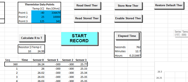
If an application requires a thermistor sensor different than the default programmed one, a User Thermistor can be programmed. User Thermistor programming is only available through the protocol communication method. User Thermistor must be a 10K Ohm thermistor with J-curve characteristic. J-curve characteristic means, the thermistor has a parabolically descending resistance as the temperature increases. If the specified accuracy in the datasheet is desired, a thermistor with 1% accuracy at 25°C or 0.2°C accuracy should be used. Programming accuracy (Resistance to Temperature mapping) for the programmed User Thermistor can be tested with the Excel Communication Tool, which is described in the Programming Tool section below, before use for suitability in your application. Programming is fairly simple. Three thermistor temperature points are used for programming -40°C, +25°C, and +125°C. There are three commands to be executed in Protocol mode.
1. Write resistances for the specified temperatures
2. Write specified temperatures that correspond to the resistances
3. Enable User Thermistor
Specified temperatures (-40°C, +25°C, and +125°C) are not required for programming, however, it is necessary to obtain the specified measurement range and accuracy. It is always possible to revert back to the default thermistor program by disabling the User Thermistor. The programmed User Thermistor will stay in the memory until re-enabled or re-written by another User Thermistor characteristic. All channels use the same thermistor characteristic that is active. Please refer to Protocol Specification for the details of the implementation.
Programmable Power Dissipation Coeeficients
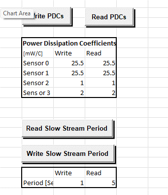
In a thermistor, Power Dissipation Coefficient (PDC) specify inaccuracy power dissipation causes in a measurement, which is influenced by the measuring circuit. Encapsulation type of a thermistor has a great influence on PDC. When a thermistor encapsulated as a probe, usually the PDC effect becomes insignificant due to the heatsinking, which is the case in the default thermistor used and provided with Mavi Circuits’ products. Therefore, default thermistor program does not use Power Dissipation Coefficients. However, other forms of encapsulations for the same thermistor are available which may require the use of PDCs. Each sensor channel is assigned with a separate PDC, therefore, with the same thermistor characteristic different encapsulations (packages/probes) for different channels can be used.
Note that when inaccuracy introduced is significant by the PDC, it affects the middle range of the measurement range the most and its effect decreases exponentially toward the high and low ends of the measurement range. Thermistors in general have Power Dissipation Coefficient (PDC) in the range of 1-25mW/°C. Its effect is more pronounced if PDC value is on the low end of the spectrum. For instance, if a thermistor has 2mW/°C PDC, that means there is 1°C error in the measurement when the power dissipation on the thermistor reaches to 2mW. PDC effect decreases as the PDC increases. It is important to point out PDCs are specified in a specific mounting case such as leads of the thermistor at certain length in a still air. If the specified mounting and the ambient conditions change, the specified PDC changes, which requires adjustment in PDC.
As an example, thermistor with the part number 103JG1F from Littlefuse is in a DO-35 axial package, which uses the same thermistor as in the provided/recommended thermistor probe with our products. It’s PDC is 2mW/°C. The PDC effect will contribute 0.625°C error to the reading at 42°C, which is the peak error for the entire range. At 2°C and 92°C, the error contribution due to PDC will drop approximately 50%. This example only applies to products from Mavi Circuits.
Programmable Slow Data Stream Period
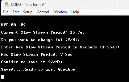
Default slow data stream period is 15 seconds. It is possible to reconfigure it to a value of 1 to 254 seconds via Protocol mode or with an ASCII PC terminal software (Tera Term, Docklight, etc.) by utilizing the rotary switch position 7, which allows to enter in the configuration menu for the slow data stream period. Please refer to Data Stream Specification or Protocol Specification for the details of this configuration.
Note that in the example picture on the right, local echo of typed characters are off.
ASCII PC Terminal Configuration Example
Programming Tool
Mavi Circuits provides Excel Communication Tool used for configuration and data logging. The programming capabilities of this excel tool can be summarized as in the following:Reading/writing unit address
Reading software version
Reading/resetting of recorded Min/Max temperatures for sensors
Reading used thermistor
Programming user thermistor
Restoring default thermistor
Reading/writing Power Dissipation Coefficients (PDCs)
Reading/writing slow data stream period
Reading elapsed time
Calculating the temperature of a given thermistor resistance based on used thermistor program: This feature is intended to be used for verifying the accuracy of the mapping for user programmed thermistor. You send a particular resistance of the thermistor, the unit sends back what the temperature is corresponding to that resistance.
Logging 1000 data points for all sensor channels and graphing them
Individual command sending capability by entering command package byte-by-byte and receiving byte-by-byte response to the send command. Useful for development and testing purposes your own application.

